The original specification was for a serial interface to multiple devices. If you look at the entries below 0x20 on the ASCII table, you can gather such gems as DC1 and SEND and some others. These were meant to control multiple devices on a single serial port. This is part of the software specification. The hardware specification implemented two serial busses in a single connector. Although most hardware never implemented the second bus, instead treating the one as bidirectional, which reduced the effectiveness of RS232. Also most software folks outside of IBM and UNIVAC seldom implemented the full control spectrum.
The line drivers were supposed to be cabable of 20ma loop current. This meant that the serial loop could pass through a chain of devices, each of which could receive and transmit data.
You could select which device(s) were active by chosing device control codes which would act on specific hardware in the receiving device. Its primary use was for communications, driving data to modems and receiving data from modems.
Generally most folks would ground the shield, which was sort of an error. What should happen is that the shield is the return path for the transmitted signal. from the DTE. Signal ground is the return path for the signal originating at the DCE. Thus properly implemented the two sides have different ground references. At the DCE (modem or printer for example) the signal ground carries the return path for the signals going to the DTE. the shield carries the signal return to the DCE. Thid implied that who ever was working on the line had to remember which line he was on. 200' of line in a high RF environment or high loss environment could build up quite a charge if it were not dealt with properly. Inside the equipment, the receiving block at the DCE would tie its input circuits between shield and a floating 5v signal. It was never really floating, as there would be a high value resistor between the shield and signal ground. The transmitting block of the DCE would be tied between DCE +5 and signal ground.
At the DTE end its transmitting block would be tied to +5 and shield to ground, with signal ground connected by a high value resistor. Its receiving block would be between a floating 5V and signal ground.
NOW all that is the theory. In practice shield ended up being connected to case grounds on both ends, and signal ground was used as the reference. This meant that you had some signal degradation on simultaneous transmit and receive, resulting in the buss being used alternately for send and receive. Also most manufacturers didn't want floating supplies, so that ended. Finally they balked at the additional $3.00 or so for the line driver bits, and used normal 7400 or DTL logic for the lines. the result was lower speeds, shorter distances, loss of noise immunity, and too many unused pins on the connector. In came the DB9, and a host of other hardware interfaces, out went the lines available for ringing (the anonymous test lines), and so went the story of slow, limited line length RS232.
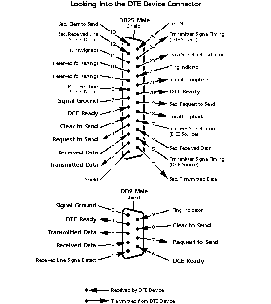
So basically all you need is the pinout in the bottom connector of the drawing (DB-9) or one of the other interfaces, short leads (generally <6') and you should be all set. There isn't much that can go wrong other than you may need a null modem connector to transpose the two serial wires. They are available all over the place, or you can simply open up the offending connector and swap them there.
Regards,
Les H
The original interface was a 25 pin device:
from: http://www.camiresearch.com/Data_Com_Basics/RS232_standard.html

--
fedora-list mailing list
fedora-list@xxxxxxxxxx
To unsubscribe: https://www.redhat.com/mailman/listinfo/fedora-list
